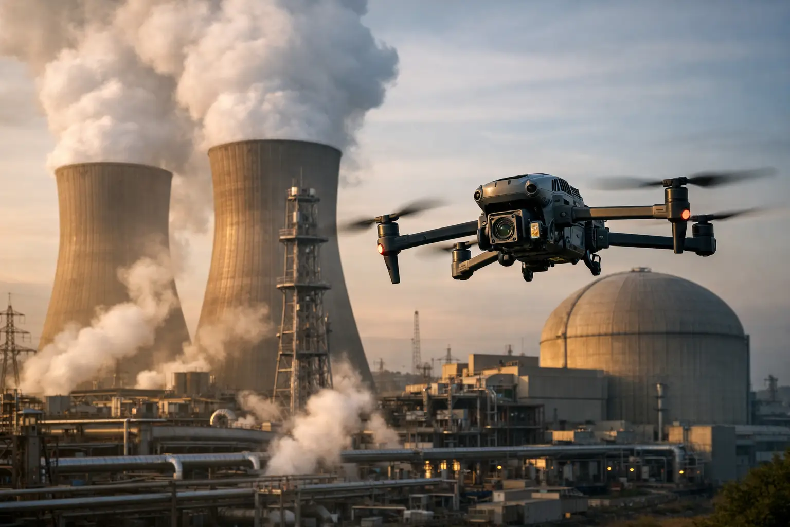
A map can look clean, detailed, and professionally rendered while still being inaccurate enough to create costly field decisions. That is why an industrial photogrammetry accuracy guide should begin with the intended use of the data, not the drone or software. A construction team tracking earthwork, an engineer documenting a cooling tower exterior, and a utility team reviewing a substation each need different levels of positional confidence, image detail, and verification.
Photogrammetry turns overlapping images into measured products such as orthomosaics, point clouds, elevation models, and 3D asset models. The process can reduce time on site and limit exposure to ladders, lifts, rope access, traffic, energized areas, or unstable terrain. But it is not a shortcut around planning. Accuracy depends on disciplined field execution, appropriate control, and a clear understanding of what the final deliverable can and cannot support.
Start With the Accuracy Requirement
The first question is not, “How accurate is drone photogrammetry?” It is, “Accurate for what decision?” If the objective is weekly construction progress documentation, consistent visual coverage and repeatable flight paths may matter more than survey-grade coordinates. If the objective is quantity tracking, as-built comparison, or design coordination, horizontal and vertical accuracy requirements must be defined before mobilization.
Accuracy is commonly described in three separate ways. Relative accuracy is how well features align with one another within the model. Absolute accuracy is how closely the model aligns with real-world coordinates. Repeatability is how consistently separate captures can be compared over time. A site may have a strong-looking, internally consistent model but poor absolute alignment if its coordinate system or control was handled incorrectly.
For industrial facilities, the acceptable tolerance also changes by asset. A rooftop documentation model may need enough detail to locate penetrations, drainage areas, and visible defects. A stockpile calculation requires reliable elevation data. A cell tower or cooling tower model requires image geometry that captures vertical surfaces and complex shapes. Treating each job as a standard overhead mapping mission can produce gaps, distortion, or unusable measurements.
What Controls Industrial Photogrammetry Accuracy?
Ground sample distance sets the detail ceiling
Ground sample distance, or GSD, is the ground size represented by each pixel. A smaller GSD generally captures finer detail, but it does not automatically guarantee better measured accuracy. Flying lower can improve image resolution, yet it may also reduce coverage efficiency, increase mission time, and create more difficult conditions around tall structures or restricted work areas.
The right GSD follows the smallest feature the team needs to identify or measure. For broad construction mapping, the needed resolution may be different from close-range documentation of concrete cracking, roof flashing, transmission hardware, or corrosion patterns. The capture plan should match the required deliverable, rather than collecting excessive imagery that increases processing time without improving the decision.
Image overlap and camera geometry matter
Photogrammetry software needs common visual features across multiple photographs to calculate position and shape. Overlap provides that shared information. Standard nadir mapping uses substantial forward and side overlap, but industrial work often requires more than a grid flown directly overhead.
Vertical walls, tanks, stacks, containment structures, tower components, and pipe racks benefit from oblique imagery captured from multiple elevations and viewing angles. These images strengthen the geometry of the model and reduce the risk of stretched or poorly reconstructed surfaces. The trade-off is additional flight planning, battery management, and careful standoff distances. Near complex assets, safety procedures, site coordination, wind conditions, and operational restrictions should govern the flight plan.
Control establishes real-world confidence
Ground control points, or GCPs, are clearly marked points with surveyed coordinates. When placed well and measured correctly, they help tie photogrammetry outputs to the required project coordinate system. They are particularly valuable when the client needs defensible absolute accuracy for mapping, grading, quantities, or comparisons with existing survey and design information.
RTK or PPK-enabled drone workflows can improve the geolocation of images and reduce the amount of control required in some conditions. They do not eliminate the need for verification. Satellite reception, base station setup, coordinate reference choices, antenna measurements, and site obstructions can all affect results. On high-value projects, independent checkpoints provide the evidence needed to assess the final output rather than simply assuming the onboard positioning performed as expected.
Control distribution is as important as the number of points. Points concentrated near one edge of a site cannot reliably constrain a large project area. They should be spread across the work zone, including the perimeter and interior where practical. On long linear corridors, distribution must reflect the length and changing terrain of the project. Control also needs to remain visible in the imagery and protected from disturbance during field operations.
Checkpoints verify, rather than influence, the model
A checkpoint is measured independently but withheld from processing alignment. After the model is built, its coordinate can be compared with the model-derived position. This provides a meaningful assessment of absolute accuracy.
That distinction matters. A low reported error on points used to build the model can indicate that the software fit those points well, but it is not the same as independent validation. For clients making operational, engineering, insurance, or project-management decisions, checkpoint reporting provides a clearer record of confidence and limitations.
Plan for the Conditions That Create Error
Industrial sites rarely provide ideal photogrammetry conditions. Metal roofs can reflect light. Uniform concrete, painted surfaces, water, glass, and repetitive structural members may offer limited visual texture for image matching. Shadows can hide features, while changing sunlight across a long mission can create inconsistent color and contrast. Wind may move vegetation, temporary materials, hanging cables, or equipment.
Field planning should account for these variables before the aircraft is launched. A pre-flight review should confirm the asset boundaries, access limitations, active operations, expected obstacles, required standoff distances, control locations, and the coordinate system requested by the client. It should also identify whether the project requires nadir imagery, oblique imagery, thermal data, close visual inspection, or a combination of deliverables.
For example, a construction site captured after heavy rainfall may contain standing water that does not represent finished grade. A solar glare condition on a metal roof can reduce usable detail. A transmission corridor may require separate capture blocks due to terrain changes and line-of-sight limitations. In each case, a professional workflow documents the condition and adjusts the collection plan instead of forcing a one-size-fits-all output.
Coordinate Systems Cannot Be an Afterthought
Many accuracy problems are not caused by image capture. They occur when data is delivered in the wrong coordinate reference system, vertical datum, unit of measure, or local site grid. A model can be internally accurate and still be offset by several feet when compared with project CAD files because the coordinate assumptions were never confirmed.
Before collection, establish whether the client needs state plane coordinates, a local grid, latitude and longitude, orthometric elevations, ellipsoidal heights, or another specified reference. Confirm units as well. Feet versus meters mistakes are avoidable, but they are not minor when data must support construction layout, earthwork review, or asset documentation.
The deliverable should clearly state its coordinate reference, control method, checkpoint results where applicable, capture date, and known limitations. This documentation makes the output more useful when it changes hands between field teams, engineers, owners, adjusters, and project managers.
Use the Right Accuracy Standard for the Deliverable
An orthomosaic, point cloud, and textured 3D model do not carry the same strengths. Orthomosaics are useful for site context, progress tracking, and plan-view measurement. Point clouds can support surface review, volumetric analysis, and integration with other spatial data. Oblique 3D models provide valuable visibility on façades and elevated assets. Each output should be selected based on the question it needs to answer.
Photogrammetry also has limits. Dense vegetation can conceal bare ground. Smooth, reflective, or transparent surfaces may reconstruct poorly. Fine cracks, small fasteners, and hidden conditions may require closer visual inspection imagery rather than a mapping model. Thermal imagery can indicate temperature differences, but it should be interpreted within the equipment, weather, emissivity, and inspection context of the asset.
For this reason, aerial data should support qualified engineering, maintenance, safety, and insurance workflows rather than be presented as a structural certification or a substitute for a required hands-on inspection. Clear boundaries protect both the project and the usefulness of the data.
A Practical Pre-Flight Accuracy Checklist
Before approving an industrial photogrammetry mission, establish these five items:
- The business decision the deliverable will support and the tolerance it requires.
- The coordinate system, vertical datum, units, and required file formats.
- The appropriate GSD, overlap, flight angles, and coverage for the asset geometry.
- The control and checkpoint plan, including who will provide survey coordinates when required.
- The site-specific hazards, operational restrictions, weather limits, and access coordination.
This planning step is often where accuracy is won or lost. It prevents a team from collecting a visually impressive dataset that cannot be aligned with the project records or relied upon for the intended analysis.
Reliable Data Comes From Disciplined Execution
Industrial photogrammetry accuracy is not a single specification printed on a drone data sheet. It is the result of matching the mission to the asset, capturing images with sufficient geometry and resolution, establishing appropriate control, and validating the output against independent checkpoints.
For complex construction, utility, energy, telecom, and industrial environments, the best approach is to define accuracy before the flight and document it after processing. Air Reel Technologies applies that field-first discipline to aerial mapping and inspection support, helping teams receive data that is organized around real operational decisions. When the required tolerance, capture conditions, and validation method are clear from the start, aerial documentation becomes a dependable part of the project record rather than another source of uncertainty.